A point‑to‑point (PTP) wireless link with Aruba APs in AOS 10 is usually implemented using an Enterprise Mesh design: one AP is the “portal” (wired side) and the other is the “point” (remote side). Aruba Central becomes the single place you define the mesh relationship, security, and how traffic should be bridged across the wireless backhaul.
What “PTP” means in AOS 10
In a classic PTP bridge, you’re extending Ethernet from Site A to Site B over a dedicated wireless link. With Aruba AOS 10, the common way to do that is:
- Mesh Portal AP: connected to the wired network at Site A.
- Mesh Point AP: installed at Site B, reaches Site A over the wireless backhaul, and presents connectivity to the remote wired device(s) via its Ethernet port(s).
Think of the wireless backhaul as the “invisible cable,” and the remote AP as the device that turns that backhaul back into usable Ethernet at the far end.
Step 1: Create the Device Group
Create an AOS 10 Device Group and name it ‘Point to Point APs‘
Add the relevant APs to the Point to Point APs group.
Step 2: Create a Management SSID (Optional)
I like to create a 2.4 GHz only network for local management. This is an optional step but helps if you need to troubleshoot onsite and forget to bring a console cable.
Under WLANs click Add SSID.
In General, enter ESSID name: P2P Management and Band: 2.4 GHz.
In VLANs, Traffic forwarding mode: Bridge, Client VLAN Assignment: Static and the VLAN ID of your Wireless Management VLAN.
In the Security tab, ensure Security Level is Personal, select WPA3-Personal Key Management and enter a passphrase.
Under Access, ensure Access Rules are Unrestricted.
Step 3: Create the Point to Point SSID
This step creates the SSID that all traffic will use between APs.
Under WLANs click Add SSID.
In General, enter ESSID name: P2P and Band: 5 GHz
In VLANs, Traffic forwarding mode: Bridge, Client VLAN Assignment: Static and the VLAN ID of your Wireless Management VLAN.
In Security, ensure Security Level is Personal, select WPA3-Personal Key Management and enter a passphrase.
In Access, ensure Access Rules are Unrestricted.
Step 4: Create Mesh at the AP Group level.
In System, Mesh, select the Mesh Band as 5 GHz and click on the + sign to create a mesh.
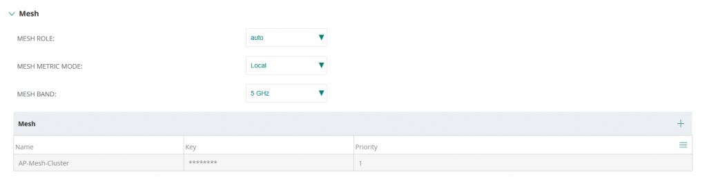
Enter the Name of the mesh cluster as AP-Mesh-Cluster and enter a key.
Step 5: Assign the APs a static IP address
In Devices, click on the Mesh Portal AP, click Device, Access Points, Edit
Give the Mesh Portal AP a name and static IP address.
Under Installation Type ensure it is set to Outdoor (if applicable)
Repeat the process for the Mesh Point AP.
Step 6: Define the Roles of each AP
Go to Per-AP level by clicking on the Mesh Portal device name. Toggle to Device, click on Config and navigate to System. Scroll to Mesh Role and change Mesh Role from Auto to Portal.
Reboot the device
Go to Per-AP level by clicking on the Mesh Point device name. Toggle to Device, click on Config and navigate to System. Scroll to Mesh Role and change Mesh Role from Auto to Point. Do not reboot the AP yet as the Portal needs to come online first.
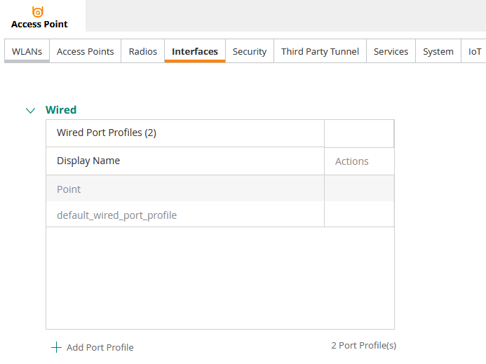
Step 7: Configure Interface of Point APs
Go to Per-AP level by clicking on the Mesh Point device name. Toggle to Device, click on Config and navigate to Interfaces.
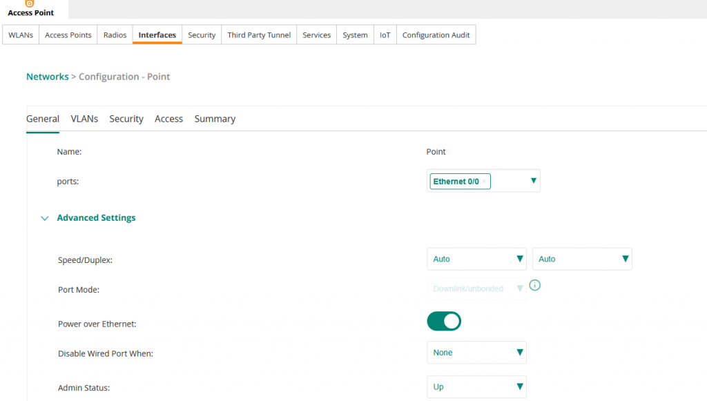
Under Wired Port Profiles, click Add Port Profile.
Name the profile Point, ensure port is set to Ethernet 0/0 and Port Mode is set to Downlink.
After saving, reboot the AP.
Validation
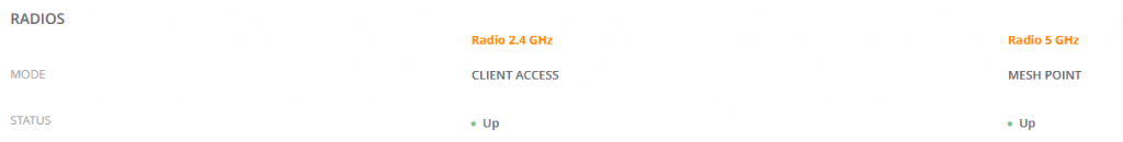
Upon reboot the Mesh Portal should come online and show MESH PORTAL under it’s Summary.
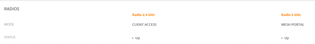
Likewise, the Mesh Point should show MESH POINT under it’s Summary.
I had a couple of issues with these during deployment. If your APs are not in the correct role, ensure the following:
- The Portal and Point APs in my experience needed to be connected to two different switches. I had both coming up and reporting Portals until I moved one to a different switch (with exactly the same configuration)
- If they are intermittently rebooting or offline, check STP on the upstream switches. In my case the link was working fine which would cause a loop in the network however, RPVST blocked specific VLANs to avoid this. The show spanning-tree command on the switch highlighted this. This proved that the Point to Point link was working fine and I was able to disconnect the uplink on the switch that the Point was connected to and prove the link worked.